It's all about organization
Introduction to Controls Wiring Basics Continued from March
|
|
|
This month, we will continue the introduction to controls wiring. For this section, I will be using the following two controllers as examples;
- TUCB24C6X2 wall mount fan coil controller
- EVCB14NIT4S unit mount VAV controller
Power Supply Wiring
The power supply must be wired with half-wave class 2 transformers. This allows for the grounding of the neutral.
Do not use full-wave transformers to power the controllers and do not ground the neutral of both transformer types.
- Power supply is connected to terminal block #1 (TB1)
- Pins #1 & #2 are used for the common (-)
- Pins #3 & #4 are used for the live 24Vac (+)
- Pins #3 & #4 are used for the live 24Vac (+)
- Note that the common is grounded
- Has only one terminal block
- Common (-) is wired to pin #1
- 24Vac is wired to pin #2
Source/Sink
Sink and Source simply identifies the 24Vac source that will be used to control the equipment.
- Jumpers "JP1" and "JP2" are set to "INT"
- Controller uses its own internal power source
- Jumpers are set to "EXT"
- Voltage comes from an external power supply
- Jumper "JP1" is used to set TRIAC Outputs 1 and 2 (TO1 & TO2)
- Jumper "JP2" is used for TRIAC Outputs 3 and 4 (TO3 & TO2)
- Can also be used when common switching is required
Some valves may require dry contacts onlt. If this is the case, simply put a jumper between a common and TO1/TO2 pin.
Unit Mount Controller
The EVCB & EFCB series are unit mount controllers. This means that most of the wiring is done locally where the
controlled unit is located. When dealing with applications that require a lot of wiring, I suggest using a wall
mount controller to cut down on the wire length, cost and labor. It is only a 3 wire connection from the controller
to the thermostat which represents the longest run you will have to do.
Temperature Sensor (10kΩ type 3) WIring
A thermistor does not have any polarity meaning that there is no “+” or “-”. It does not matter which wire goes where
as long as you have a common and an analog input connected to it.
When two temperature sensors are used but only one common is available, the sensors will have to share the same common.
This applies more for a unit mount type controller.
When working with wall mount controllers, your goal is to minimize the quantity of wires required going in the back of the thermostat. Since most of the
devices connected to the controller are either in the ceiling or in the unit control panel, it is possible to do just that.
In these examples, there are two temperature sensors connected to the controller. If we follow the logic of minimum two wires per device,
this means that we would require four wires for those sensors. If done properly, we could reduce the number of wires to two. To do so, we
require a terminal strip installed locally (near the unit) that will hold the common and the 24Vac power from the transformer.
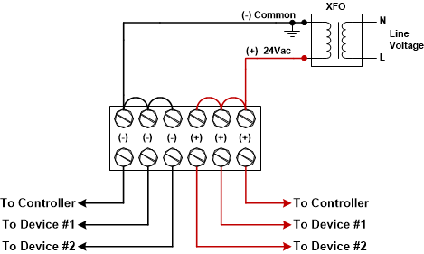
Terminal Strip
Here is an example of a terminal strip application. This type of set-up is more common when using wall mount controllers to limit
the number of wires to the thermostat and to secure the wire in place. Depending on the terminal strip, more than one wire can be
connected to each screw. Make sure the screws are tight but not too tight as this may cause the wire to break. It is always good
to pull the wire gently to make sure it is secured.
Transducers
Transducers require power to operate. Always make sure the power requirement matches the controller and/or the transformer.
An example of a transducer would be a 0-10Vdc temperature sensor. Inside the transducer is a thermistor or RTD temperature
sensor, which is read by an internal circuit board. The board interprets the signal and simulates a 0-10Vdc based on that
temperature reading. The main differences with thermistors are the 24Vac power supply and polarity. In contrary to
thermistors, transducer’s polarity must be observed.
Digital (Binary) inputs
There are two types of signals when dealing with binary inputs; dry contacts & wet contacts. Dry contacts do not have any
voltage. They simply close the circuit to obtain continuity. Wet contacts, which are more common, require 24Vac or 24Vdc to operate.
Relays can have both a normally opened and a normally closed contact. This is usually the case when dealing with occupancy sensors
and changeover switches. Verify the controller’s behavior when contacts are opened or closed. These should be described in the BACnet
guide of the product or the specification and installation instructions.
Analog Outputs
Analog inputs require at least two wires to operate; the 0-10Vdc and the common. This is the case when the device has its own power supply such as our duct heaters.
Some analog outputs will require a 24Vac to power up the device such as modulating valves.
ECM fans may require a permission or start/stop command. Even if a 10 volts signal is sent to the fan, it will remain off if the permission is not enabled.
TRIAC Outputs
These types of outputs can be used as binary contacts, floating and pulse. Even though the last two are used in a binary fashion,
they are actually simulating a modulating signal. In the floating format, two contacts are used; one to open and one to close. Note
that the actuator run time is required to operate properly. The controller uses this configuration to calculate the actuator position.
In the pulse format, the contact is closed based on a time period (most of the time they are based on a 1 second time frame).
Depending on the demand, the contact will stay closed or opened for longer periods of time. Note that pulse is only used with heating ramps.
Digital (Binary) Outputs
Unlike the TRIAC outputs, the binary are limited to two states; open and closed. They can be dry contacts or 24Vac (wet contact).
The advantage of the binary versus the TRIAC output is that it can be used to close digital inputs.
The TRIAC & binary outputs can handle ON/OFF devices as well as staged devices.
For the last section, I wanted to show an example of External Signal (Sink). A transformer relay does not require power or a
24Vac contact to be activated. It only requires the contact to close in order to pass the 24Vac/Vdc generated by the transformer
to power up the relay. When the relay closes, the heater is energized.
|