It’s all about organization:
Control Wiring Basics
|
|
|
This month’s Techtime covers the information required to be able to wire various
equipment to our controllers. Before proceeding, remember that Neptronic controllers
are configurable, which means two things:
-
Even though the device is connected to the right type of input or output, this
does not mean that it is the correct configuration.
-
If the configuration you are looking for does not exist, it will most likely not work properly.
For example:
-
Equipment: Duct Heater
-
Type: Output
-
Function: Heating Ramp
-
Control Signal: 0-10Vdc
Note that valves can be direct or reverse acting. This information is very
important since not all controllers have the ability to reverse the signal. This issue
could be solved by using an external relay if the controller is already installed.
he same applies to sensors, transducers, and relays:
-
Equipment: STC8-11 temperature sensor
-
Type: Input
-
Function: Changeover
-
Control Signal: 10kΩ type 3
Once the equipment list is completed, you must refer to the Specification &
Installation instructions to identify the possible terminals to be used. This
document details the default configurations of the controller and the specific
order in which they should be programmed. Sometimes, we can find a preconfigured
input or output that matches the equipment requirements. This step allows us to
reduce configuration time for the client. If there are no defaults available,
then identify which terminal you will be using for the device.
Note concerning the Commons
All of the equipment that needs to be wired requires at least two wires; common & signal.
The common is the base or reference for the control signal. When you have multiple devices on
the same controller, it is important that the common is the same for all. This is why we often
recommend grounding the neutral leg of the transformer. This is especially true when multiple
transformers are used on the same controller or multiple controllers connected together for a
specific function, such as night setback.
When the transformer's neutral is not grounded (also referred to as a "floating transformer"),
it is possible for the common to have residual charge. This residual charge will influence the
signal sent to the devices from the controller. The voltage sent from the controller will not be
the same as the voltage measured at the device terminal strip.
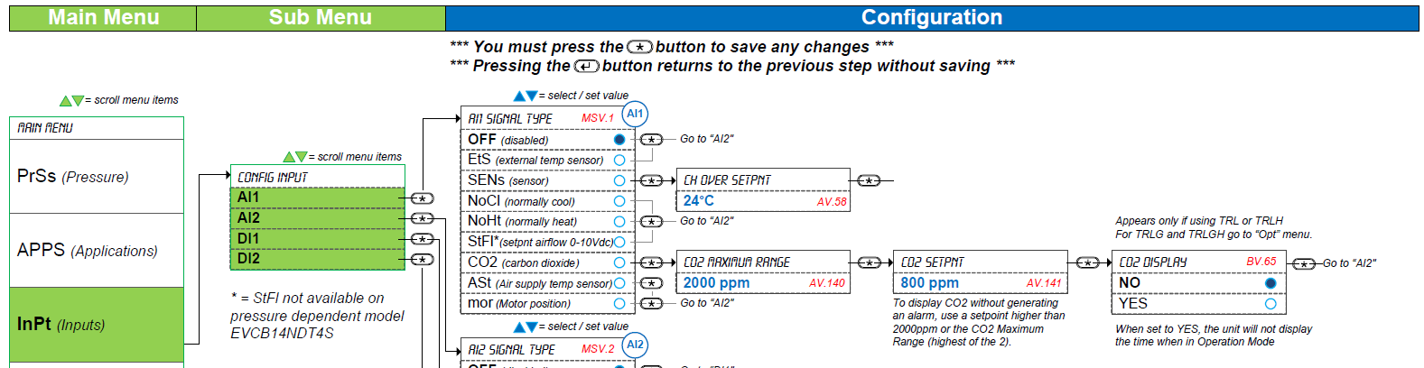
The configuration structure is a little different from the TUCB and EFCB series. It is the only
controller with 2-pipe or 4-pipe configuration which is equivalent to changeover ramp in other
controllers. It is also the only controller that uses Reheat which is equivalent to Heating Ramp 2.
Note that all the commons on the Neptronic controllers are all internally linked together.
Applying a voltage on one common will affect the entire controller’s behavior.
Signal
Analog signals are influenced by external power sources such as light ballasts and variable frequency drives
(VFD). Staying away from these electrical fields is important. If you believe there might be some electrical
interference, a shielded wire can be used. Digital (Binary) signals are also affected, but not enough to
make any significant difference.
Types of Inputs & Outputs
Digital or Binary Input (DI/BI): This type of input can be used as a dry contact (voltage free) or a wet
contact (24Vac contact). It can be configured as a changeover switch, occupancy or night setback contact.
Some controllers offer safety options such as airflow switch, door/window contact and a dirty filter switch.
Controller override and heat override are some of the new features found on the second generation EVC and
EFC controllers.
Analog Input (AI): This type of input can be configured as temperature (external/remote, discharge
and/or changeover). On some models, CO2 and humidity sensors may be available. All of our controllers
use a 10kΩ type 3 or G thermistor for temperature, and some models can accept 0-10Vdc signals.
Universal Input (UI): This type of input can handle multiple signals. It can be configured for
thermistors, modulating 0-10Vdc or it can be a binary contact.
Digital or Binary Output (DO/BO): This type of output is used with On/Off signals and stage control.
It can be configured for heating and/or cooling but can also be used for fan speeds and On/Off humidifier.
Analog Output (AO): This type of output is used when with modulating signals such as 0-10Vdc or
2-10Vdc. It can be configured for heating and/or cooling but can also be used for ECM fan speed
modulation and humidifier control.
TRIAC Output (TO): This type of output is used with On/Off or pulse signals as well as staged
control. It can also be used with floating signals which is a form of On/Off to simulate a modulating
signal. They can be configured as heating and/or cooling but can also be used for fan permission or start/stop.
Other Device Power Supply
Some equipment may require an additional wire to power up the device. Depending on the model, the 24Vac power
supply can be from the controller board or connected to the transformer directly.
Power from the controller board
Advantage: Usually simpler to connect since the terminal strip is already present (control board).
Disadvantage: The traces on the controller’s printed circuit board limit the amount of
Volt-Ampere (VA) available and may not be sufficient for the device.
Power from the transformer
Advantage: The amount of Volt-Ampere (VA) available only depends on the transformer size. If the
transformer has enough capacity, it will work.
Disadvantage: The addition of a terminal strip is required to make the distribution possible.
Wire Gauge
The wire gauge for controls is found on the specification sheet of the controller.
Power wiring
-
18 AWG (0.8 mm2) minimum
-
Binary signals maximum length is 300' (90m)
-
Analog signals maximum length is 100' (30m)
Thermostat to Controller (EVCB & EFCB series)
-
3 wire connection 18 AWG (0.8 mm2) minimum
-
Maximum 50ft (15m) between controller and thermostat
Power wiring
-
24 AWG twisted-shielded cable (Belden 9841 or equivalent).
-
Maximum network length 4000' (1200m) (Refer to the BACnet Guide available on the Neptronic website)
|