Wiring 101
Power Supply and Sink/Source
Sometimes, controllers' power supply and wiring can seem complicated. However, it is crucial to have a good understanding of the correct way to do
it in order to avoid potential issues.
Here is a quick explanation of NeptronicÕs EVC and EFC controllers wiring diagrams to help you maintain or increase a good comprehension of how they should be
wired. We will also make the distinction between source or sink on the TRIAC outputs.
EVC (VAV Unit Controller)
Main Power Supply
Let us start with the EVC. Terminal block "TB1" at the bottom right hand side of the controller has four (4) terminal screws; two (2) "24VAC" and two (2) "COM".
The line side of the transformer (the one that gives 24Vac) must be connected to either terminal 3 or terminal 4 identified by "24VAC". The ground side of the
transformer must be connected to terminal 1 or terminal 2 identified by "COM". As long as theses two rules are observed, it does not matter if you connect to
terminals 1 & 3, 2 & 4, 1 & 4 or 2 & 3. In the example shown below, we chose terminals 1 & 3. The extra terminals may be used to power external equipment that
requires constant 24Vac such as valve actuators, CO2 sensors, timers, etc.
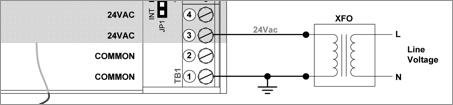
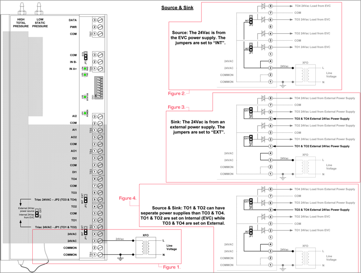
Figure 1. See full diagram below
TRIAC Source (Internal)
Sink and Source is simply to identify the 24Vac source that will be used to control the equipment. When using "Source", the jumpers "JP1" and "JP2" are set to "INT"
which means internal. In other words, the voltage comes from the EVC.
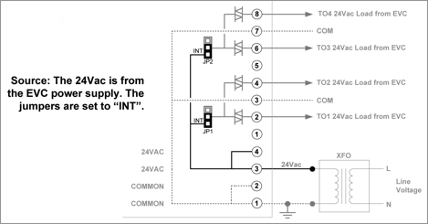
Figure 2. See full diagram below
TRIAC Sink (External)
When "Sink" is required, the voltage comes from an external power supply and the jumpers should be set to "EXT". Jumper "JP1" is
used to set TRIAC Outputs 1 and 2 (TO1 & TO2) and jumper "JP2" is used for TRIAC Outputs 3 and 4 (TO3 & TO4).
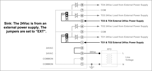
Figure 3. See full diagram below
TRIAC Sink + Source
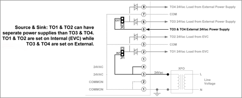
Figure 4. See full diagram below
EFC (Fan Coil Unit Controller)
There are three types of power supply for the EFC; 24Vac, 120Vac and 240Vac.
Low Voltage Supply (24Vac)
Out of the three models, the 24Vac requires a little more attention. In order to connect power to EFCB10WQx, you must wire the line side of the transformer to
terminal 1 of terminal block TB4 identified by "Vac IN". The ground side of the transformer is wired to terminal 2 of the same terminal block identified by
"Return". This will power the Fan and the Digital Outputs on the board. In order to have power on the remaining board, the 24Vac must also be wired to
terminal block TB11 located on the bottom left hand side of the controller. It is the only model that must be wired on both sides of the controller.
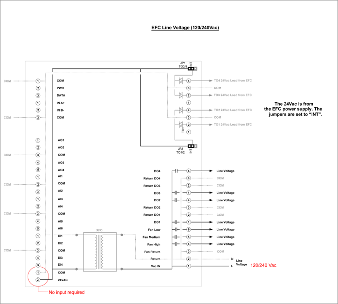
Line Voltage Supply (120/140Vac)
The EFCB11WQx and EFCB12WQx models have an integrated transformer that transfers line voltage to 24Vac to the remaining board. Refer to the drawings below to
better understand the power road maps.
The Sink and Source for the TRIAC Outputs work the same way as the EVC models. Refer to the EVC section above.