CMU: The Basics of the MAC Board
Neptronic's Make-Up Air Controller, referred to as MAC, serves as a fundamental component within our innovative Compact Make-Up Air Unit (CMU).
The MAC board, which can be called the brain of the CMU, helps the system in enhancing the Indoor Air Quality (IAQ) by delivering air that is
fresh, filtered, and pre-heated through ductwork. However, while the technical specifications of the CMU, such as
airflow requirements and heating capacities, are pivotal in selecting the appropriate model for a given application,
the effectiveness of these units ultimately relies on their control strategies.
In this article, we discuss the standard features of the CMU by delving into the MAC board’s basic control capabilities.
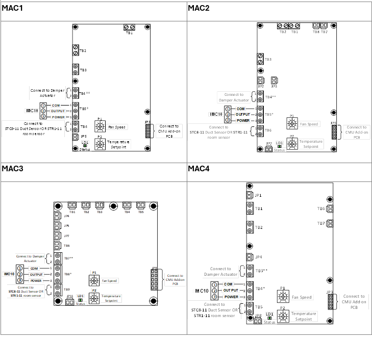
Remote Temperature Sensor Connection
The remote temperature sensor connection is a critical aspect of the CMU's functionality, ensuring accurate temperature monitoring for
effective operation. By default, the CMU is equipped with a remote temperature sensor, and users can choose between
two types: the STC8-11 discharge air duct temperature sensor, or the STR1-11 room air temperature sensor.
The remote temperature sensor must be appropriately wired to its designated terminal block on the MAC board even if the COM board
is used for the application. Failure to establish this connection results in the CMU not initiating its operational cycle.
IMC10 Connection
The IMC10 connection on the MAC board of the CMU serves as a key feature for additional control and interlocking capabilities.
The MAC board has a designated terminal block specifically for connecting an IMC10 room control switch. If no IMC10 is used,
a jumper must be placed between pins 1 and 2 of that T-block (done by default at the factory). Alternatively,
the two pins (1 and 2) on the terminal block can be repurposed as an enable/disable contact (e.g., by wiring an
SIH-150 current switch to interlock the CMU with an exhaust fan). If the circuit between pins 1 and 2 opens,
it results in the CMU being disabled.
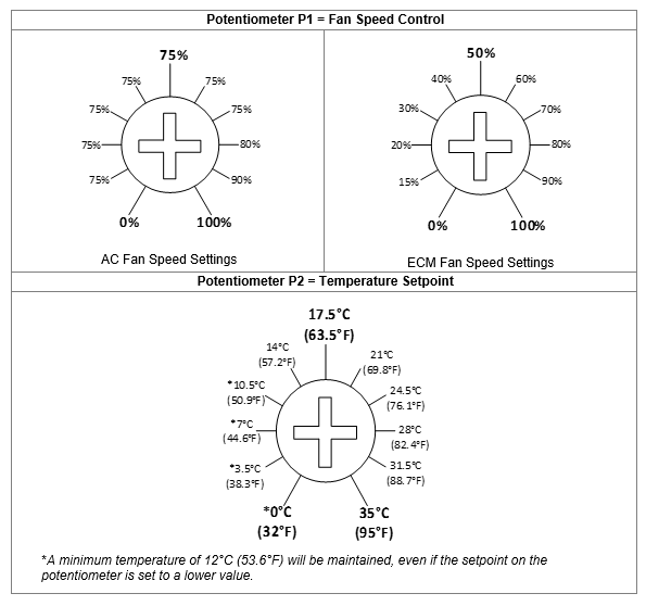
Fan Speed and Temperature Setpoint Adjustment
Central to the MAC board's capabilities are two essential potentiometers. The first, P1, allows for the adjustment of fan speed,
providing users with the flexibility to tailor airflow to specific requirements. Meanwhile, P2 allows users to
set and fine-tune temperature setpoints, ensuring precise control over the heating of the CMU system. The minimum
fan speed achievable via P1 depends on the type of fan the unit came with: The minimum fan speed for AC is 75% and
for ECM, it is 15%.
Damper Actuator Connection:
During normal operation, the MAC board within the CMU closes an internal, 24VAC-rated dry contact which is capable of handling up to 1A of
current. This terminal block can be used to drive a damper actuator or even as an auxiliary switch to start any other
remote device based on the application’s needs (e.g., an exhaust fan).
Add-On PCB Connection:
The MAC board boasts a dedicated terminal, strategically positioned to integrate with the CMU-COM add-on control board. This addition serves
as a gateway to a realm of advanced control strategies thanks to its configurable Inputs and Outputs (I/Os), connection for
a remote TDF user-interface module and BACnet/Modbus communication.
Although optional for CMUs with AC fans, if an AC model was ordered without the COM board, it can be added in the future, making the “basic”
CMU upgradeable for advanced control strategies and/or BACnet/Modbus integration.
This board comes standard on all CMUs equipped with Electronically Commutated Motor (ECM) fans.
Status LED Sequence:
The Status LED (LD1) on the MAC offers an intuitive output sequence to indicate specific alarm types. By providing a clear method of
conveying alarm information, the MAC ensures that users can navigate troubleshooting effortlessly.
Status | LED Output |
Remote Temperature Sensor Fault | Blinks 5 times and stays ON for 5 seconds. |
Electronic Airflow Sensor Fault | Blinks 10 times and stays ON for 10 seconds. |
Automatic/Manual Cut-out Trip | Blinks 15 times and stays ON for 15 seconds. |
Normal Operation | Blinks once every 2 seconds. |
Other Scenarios can include:
- Error in Feedback for ECM Fans
- Incorrect configuration of the IO's on the COM board
- Communication error between the Add-on and Host Boards
- No heat detection (when failing to achieve the desired temp. setpoint within the programmed delay and dead band)
And so on.
|
LED stays on continuously till the alarm is reset.
|
Remote viewing/identification of any triggered alarm is possible with the add-on CMU-COM circuit
board by connecting it to a communication network (BACnet/Modbus).
For more information on our Compact Make-Up Air Unit, please refer to the relevant CMU documents on
our Documentation page.