What's the Difference?
2 Pipe vs 4 Pipe Fan Coil
There are many questions that arise when setting up a fan coil controller. Most of these interrogations come when setting up a TFC series
controllers. While in the configuration of the TFC, one of the first settings asks if it is a 2 pipe or 4 pipe system.
In order to clarify the differences, we will expose these two concepts.
2 Pipe Fan Coil
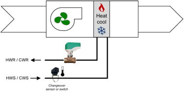
The 2 pipe system consists of a single water coil connected to two pipes (supply and return) and one valvle that can serve as either chill water
coil or hot water coil depending on the mode of the system. This type of fan coil cannot cool and heat at the same time and is dependent of the actual mode of
the building.
The 2 pipe fan coil requires a changeover sensor, usually a strap-on temperature sensor installed on the water supply, to determine the mode
of the system.
These units can be equiped with an auxiliary electric heater to compensate the limitations of the system.
4 Pipe Fan Coil
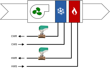
The 4 pipe system consists of two separate cooling and heating water coils. Each coil has its own dedicated set of pipes (supply and return) and
valve. This type of fan coil can cool and heat at the same time and is not dependant of the actual mode of the building.
Contrarely to the 2 pipe system, the 4 pipe fan coil does not require a changeover sensor since both hot and chill water is available.
These units can be equiped with an auxiliary electric heater to boost the heating capacity (if required).
The 4 pipe fan coil can also use a chill water coil and an electric or gas heater. As long as the cooling and heating are independent of each other,
the system will be a 4 pipe configuration.
Not all fan coils are equipped in this manner but the concept remains. The important thing to remember is that for a two pipe fan coil, a changeover sensor is
required to determine the system mode (cooling or heating). In other words, the fan coil is dependent of the system mode. If cooling is available and no
electric reheat coil is present, then the fan coil can only cool. If heating is available, no cooling is possible.
If no changeover sensor is required, this means that system falls automatically on the 4 pipe system. The 4 pipe system has two available sources
(heating and cooling) which makes the fan coil independent of the system mode. Unlike to the 2 pipe system, it can cool and heat at the same time allowing for
dehumidification to occur.
TFC/TFH series controller options
This is the configuration required when setting up an analog valve in a 2 pipe fan coil.
- AO1: Modulating valve
- AI2: Changeover sensor or switch
- TO1 & TO2 are not used
- AO2 is not used
This is the configuration required when setting up an On/Off valve in a 2 pipe fan coil.
- TO1: On/Off valve
- AI2: Changeover sensor or switch
- TO2 is not used
- AO1 & AO2 are not used
This is the configuration required when setting up an Floating valve in a 2 pipe fan coil.
- TO1 & TO2: Floating valve
- AI2: Changeover sensor or switch
- AO1 & AO2 are not used
| 2 Pipe |
Analog |
On/Off |
Floating |
| Terminals |
Fan option |
analog |
1 spd |
2spd |
3spd |
analog |
1 spd |
2spd |
3spd |
analog |
1 spd |
2spd |
3spd |
| TB1 |
1 |
Common |
Common |
Common |
Common |
| 2 |
24 VAC |
24 Vac |
24 Vac |
24 Vac |
| 3 |
Common Triac |
Common Triac |
Common Triac |
Common Triac |
| 4 |
Triac output 1 (TO1)
Floating output 1 |
- |
2 Pipe on/off |
2 Pipe floating (close) |
| 5 |
Triac output 2 (TO2)
Floating output 1 |
- |
- |
2 Pipe floating (open) |
| 6 |
Triac output 3 (TO3) Reheat |
Local reheat (optional) (on/off or pulse) |
Local reheat (optional) (on/off or pulse) |
Local reheat (optional) (on/off or pulse) |
| 7 |
Common Relay |
- |
Common Relay |
- |
Common Relay |
- |
Common Relay |
| 8 |
Digital output 1 (DO1) |
- |
- |
- |
High |
- |
- |
- |
High |
- |
- |
- |
High |
| 9 |
Digital output 2 (DO2) |
- |
- |
High |
Med |
- |
- |
High |
Med |
- |
- |
High |
Med |
| 10 |
Digital output 3 (DO3) / Analog Fan Speed (AO4) |
Fan analog |
1 spd |
Low |
Low |
Fan analog |
1 spd |
Low |
Low |
Fan analog |
1 spd |
Low |
Low |
| 11 |
Occupancy Sensor (DI1) |
Occupancy Sensor (optional) |
Occupancy Sensor (optional) |
Occupancy Sensor (optional) |
| 12 |
External Temp. Sensor (AI1) |
External Temp. Sensor (optional) |
External Temp. Sensor (optional) |
External Temp. Sensor (optional) |
| 13 |
External Changeover (AI2) |
External Changeover |
OExternal Changeover |
External Changeover |
| 14 |
Analog output 1 (AO1) |
2 Pipe analog |
- |
- |
| 15 |
Analog output 2 (AO2) |
- |
- |
- |
| 16 |
Analog output 3 (AO3) Reheat |
Local reheat analog (optional) |
Local reheat analog (optional) |
Local reheat analog (optional) |
Since the cooling and heating are independent from each other, the 4 pipe fan coil allow the signals to be different as well. While in the configuration process, you are required to identify what signal is used for cooling and heating (Analog, On/Off or Pulse).
| 4 Pipe |
Cool & Heat Analog |
Cool & Heat On/Off |
Cool Analog-Heat On/Off or pulse |
Cool On/Off - Heat Analog |
| Terminals |
Fan option |
analog |
1 spd |
2 spd |
3 spd |
analog |
1 spd |
2 spd |
3 spd |
analog |
1 spd |
2 spd |
3 spd |
analog |
1 spd |
2 spd |
3 spd |
| TB1 |
1 |
Common |
Common |
Common |
Common |
Common |
| 2 |
24 VAC |
24 Vac |
24 Vac |
24 Vac |
24 Vac |
| 3 |
Common Triac |
Common Triac |
Common Triac |
Common Triac |
Common Triac |
| 4 |
Triac output 1 (TO1)
Floating output 1 |
- |
4 Pipe on/off |
- |
4 Pipe on/off cool |
| 5 |
Triac output 2 (TO2)
Floating output 1 |
- |
4 Pipe (on/off or pulse) heat |
4 Pipe (on/off or pulse) heat |
- |
| 6 |
Triac output 3 (TO3) Reheat |
Local reheat (optional) (on/off or pulse) |
Local reheat (optional) (on/off or pulse) |
Local reheat (optional) (on/off or pulse) |
Local reheat (optional) (on/off or pulse) |
| 7 |
Common Relay |
- |
Common Relay |
- |
Common Relay |
- |
Common Relay |
- |
Common Relay |
| 8 |
Digital output 1 (DO1) |
- |
- |
- |
High |
- |
- |
- |
High |
- |
- |
- |
High |
- |
- |
- |
High |
| 9 |
Digital output 2 (DO2) |
- |
- |
High |
Med |
- |
- |
High |
Med |
- |
- |
High |
Med |
- |
- |
High |
Med |
| 10 |
Digital output 3 (DO3) / Analog Fan Speed (AO4) |
Fan analog |
1 spd |
Low |
Low |
Fan analog |
1 spd |
Low |
Low |
Fan analog |
1 spd |
Low |
Low |
Fan analog |
1 spd |
Low |
Low |
| 11 |
Occupancy Sensor (DI1) |
Occupancy Sensor (optional) |
Occupancy Sensor (optional) |
Occupancy Sensor (optional) |
Occupancy Sensor (optional) |
| 12 |
Ext. Temp Sensor (AI1) |
External Temp. Sensor (optional) |
External Temp. Sensor (optional) |
External Temp. Sensor (optional) |
External Temp. Sensor (optional) |
| 13 |
External Changeover (AI2) |
- |
- |
- |
- |
| 14 |
Analog output 1 (AO1) |
4 Pipe analog cool |
- |
4 Pipe analog cool |
- |
| 15 |
Analog output 2 (AO2) |
4 Pipe analog heat |
- |
- |
4 Pipe analog heat |
| 16 |
Analog output 3 (AO3) Reheat |
Local reheat analog (optional) |
Local reheat analog (optional) |
Local reheat analog (optional) |
Local reheat analog (optional) |
You can look at the original instruction document here:
http://neptronic.com/Controls/PDF/TFC24F3XYZ1-121112.pdf
The EFC series controllers do not have this type of settings. To setup a 2 pipe fan coil, the Changeover Ramp (COR) must be used
and a changeover sensor or switch must be installed and configured.
In conclusion;
2 pipe fan coil uses 1 water coil to heat or cool and is dependent of the system mode. It requires a changeover sensor or switch.
4 pipe fan coil have two distinct cooling and heating coils. It does not require a changeover sensor or switch. It is also independent from the system mode.